- 您现在的位置:买卖IC网 > Sheet目录299 > 71M6521BE-IGTR/F (Maxim Integrated)IC ENERGY METER 8K FLASH 64-LQFP
�� �
�
�71M6521BE�
�Energy� Meter� IC�
�DATA� SHEET�
�JANUARY� 2008�
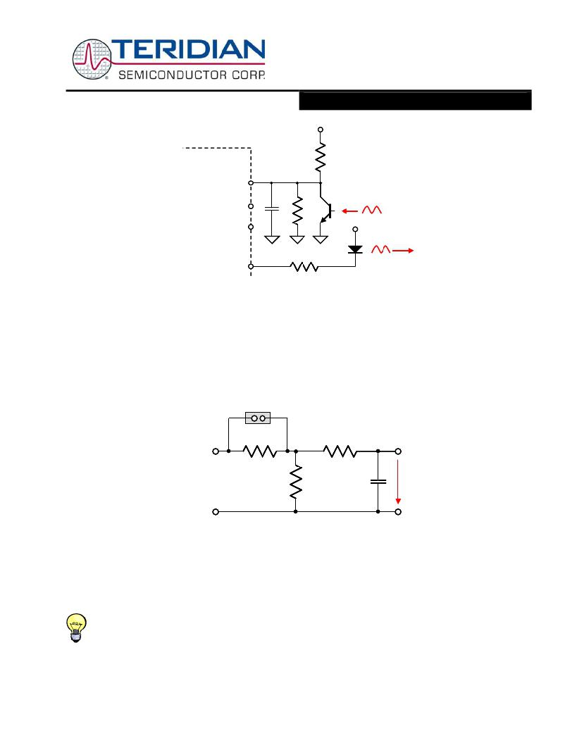
�V3P3SYS�
�71M6521BE�
�R� 1�
�OPT_RX�
�100pF�
�10k� ?�
�Phototransistor�
�V3P3SYS�
�OPT_TX�
�R� 2�
�LED�
�Figure� 34:� Connection� for� Optical� Components�
�Connecting� V1� and� Reset� Pins�
�A� voltage� divider� should� be� used� to� establish� that� V1� is� in� a� safe� range� when� the� meter� is� in� mission� mode� (V1� must� be� lower�
�than� 2.9V� in� all� cases� in� order� to� keep� the� hardware� watchdog� timer� enabled).� For� proper� debugging� or� loading� code� into� the�
�71M6521BE� mounted� on� a� PCB,� it� is� necessary� to� have� a� provision� like� the� header� shown� above� R1� in� Figure� 35.� A� shorting�
�jumper� on� this� header� pulls� V1� up� to� V3P3� disabling� the� hardware� watchdog� timer.�
�The� parallel� impedance� of� R1� and� R2� should� be� approximately� 20� to� 30k� Ω� in� order� to� provide� hysteresis� for� the� power� fault�
�monitor.�
�V3P3�
�R� 1�
�R� 3�
�5k� ?�
�R� 2�
�C� 1�
�100pF�
�V1�
�GND�
�Figure� 35:� Voltage� Divider� for� V1�
�Even� though� a� functional� meter� will� not� necessarily� need� a� reset� switch,� it� is� useful� to� have� a� reset� pushbutton� for� prototyping,�
�as� shown� in� Figure� 36,� left� side.� The� RESET� signal� may� be� sourced� from� V3P3SYS� (functional� in� MISSION� mode� only),�
�V3P3D� (MISSION� and� BROWNOUT� modes),� VBAT� (all� modes,� if� battery� is� present),� or� from� a� combination� of� these� sources,�
�depending� on� the� application.� When� the� 71M6521BE� is� used� in� an� EMI� environment,� the� RESET� pin� should� be� protected� by�
�the� external� components� shown� in� Figure� 36,� right� side.� R� 1� should� be� in� the� range� of� 100� Ω� and� mounted� as� closely� as� possible�
�to� the� IC.�
�Since� the� 71M6521BE� generates� its� own� power-on� reset,� a� reset� button� or� circuitry,� as� shown� in� Figure� 36,� left� side,� is�
�only� required� for� test� units� and� prototypes.�
�V1.0�
�?� 2005-2008� TERIDIAN� Semiconductor� Corporation�
�Page:� 65� of� 97�
�发布紧急采购,3分钟左右您将得到回复。
相关PDF资料
71M6533G-IGTR/F
IC ENERGY METER 3PH 100LQFP
71M6543F-IGT/F
IC ENERGY METERING
71M6545-IGT/F
IC ENERGY METERING
720-10007-00300
CBL D-SUB 9PIN FMAL-25PIN FML 3M
720-10010-00025
CBL DSUB 9PIN FML-25PIN MAL .25M
720-10020-00300
CBL DSUB 9PIN FML-9PIN MALE 3M
720-10021-00300
CBL DSUB 9PIN FML-9PIN FEMAL 3M
72231-0881
8 POS T/P SHLD 4 GR ASSY
相关代理商/技术参数
71M6521BE-IGTR/F1
功能描述:计量片上系统 - SoC
RoHS:否 制造商:Maxim Integrated 核心:80515 MPU 处理器系列:71M6511 类型:Metering SoC 最大时钟频率:70 Hz 程序存储器大小:64 KB 数据 RAM 大小:7 KB 接口类型:UART 可编程输入/输出端数量:12 片上 ADC: 安装风格:SMD/SMT 封装 / 箱体:LQFP-64 封装:Reel
71M6521DE
制造商:TERIDIAN 制造商全称:TERIDIAN 功能描述:Energy Meter IC
71M6521DE-DB
制造商:Maxim Integrated Products 功能描述:Development Boards & Kits - 8051 71M6521DE Demo Brd
71M6521DE-IGT/F
功能描述:计量片上系统 - SoC Residential Energy Meter IC RoHS:否 制造商:Maxim Integrated 核心:80515 MPU 处理器系列:71M6511 类型:Metering SoC 最大时钟频率:70 Hz 程序存储器大小:64 KB 数据 RAM 大小:7 KB 接口类型:UART 可编程输入/输出端数量:12 片上 ADC: 安装风格:SMD/SMT 封装 / 箱体:LQFP-64 封装:Reel
71M6521DE-IGT/F1
功能描述:计量片上系统 - SoC
RoHS:否 制造商:Maxim Integrated 核心:80515 MPU 处理器系列:71M6511 类型:Metering SoC 最大时钟频率:70 Hz 程序存储器大小:64 KB 数据 RAM 大小:7 KB 接口类型:UART 可编程输入/输出端数量:12 片上 ADC: 安装风格:SMD/SMT 封装 / 箱体:LQFP-64 封装:Reel
71M6521DE-IGTR/F
功能描述:计量片上系统 - SoC Residential Energy Meter IC RoHS:否 制造商:Maxim Integrated 核心:80515 MPU 处理器系列:71M6511 类型:Metering SoC 最大时钟频率:70 Hz 程序存储器大小:64 KB 数据 RAM 大小:7 KB 接口类型:UART 可编程输入/输出端数量:12 片上 ADC: 安装风格:SMD/SMT 封装 / 箱体:LQFP-64 封装:Reel
71M6521DE-IGTR/F1
功能描述:计量片上系统 - SoC
RoHS:否 制造商:Maxim Integrated 核心:80515 MPU 处理器系列:71M6511 类型:Metering SoC 最大时钟频率:70 Hz 程序存储器大小:64 KB 数据 RAM 大小:7 KB 接口类型:UART 可编程输入/输出端数量:12 片上 ADC: 安装风格:SMD/SMT 封装 / 箱体:LQFP-64 封装:Reel
71M6521DE-IM/F
功能描述:计量片上系统 - SoC Residential Energy Meter IC RoHS:否 制造商:Maxim Integrated 核心:80515 MPU 处理器系列:71M6511 类型:Metering SoC 最大时钟频率:70 Hz 程序存储器大小:64 KB 数据 RAM 大小:7 KB 接口类型:UART 可编程输入/输出端数量:12 片上 ADC: 安装风格:SMD/SMT 封装 / 箱体:LQFP-64 封装:Reel